CME Recognition
Recognised design signatory for matters relating to naval architecture
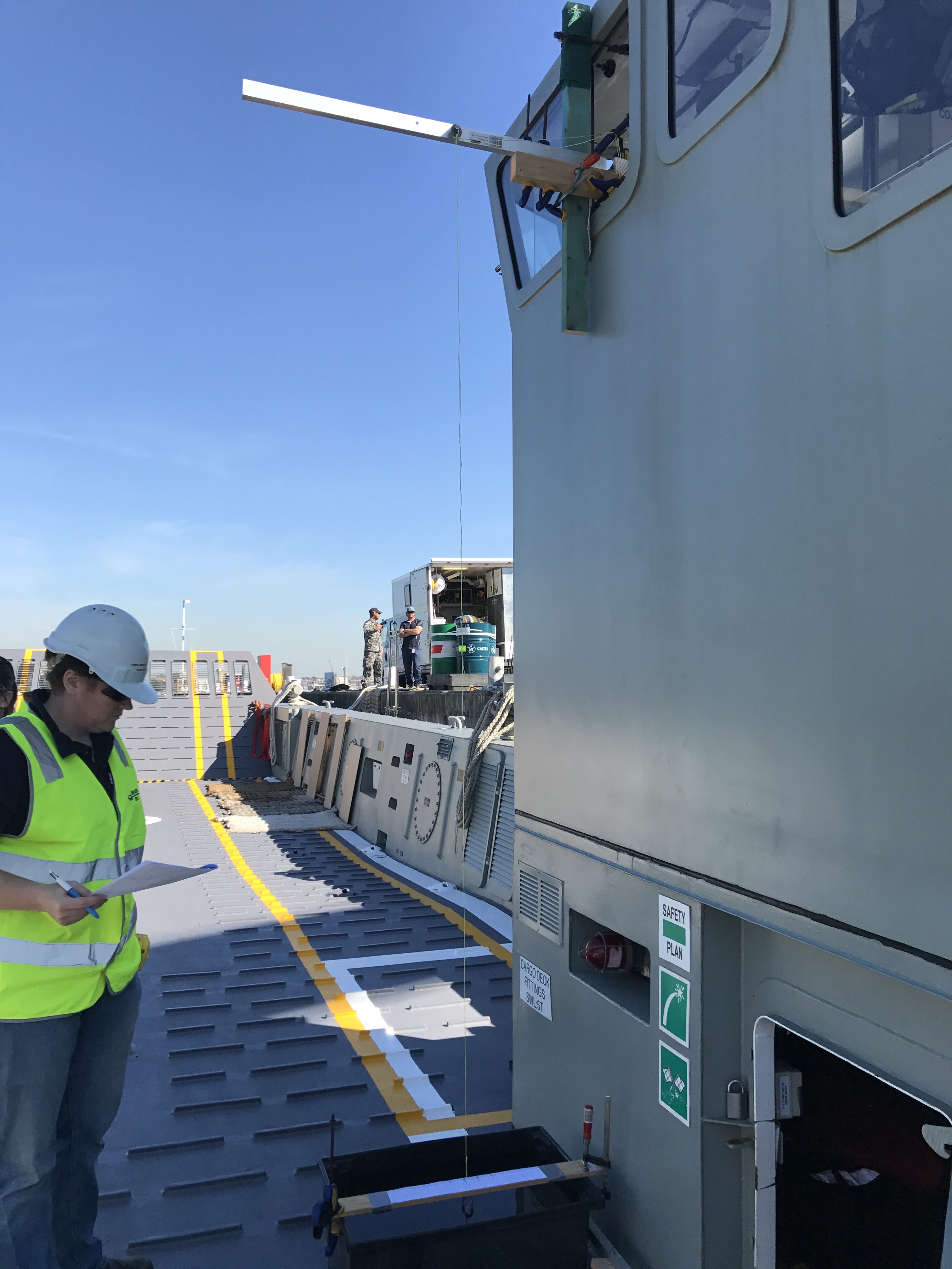
Outboard Cradle
The MCDSPO requested JBD to design a cradle to transport outboard engines to and from the boats in the water, and to assist lowering and mounting them onto the boats. This required the structure to be lightweight, mobile, capable of safely holding the engine whilst in transport and the capacity to safely lower and lift the outboard engines.
Once the aluminium design was finalised, a 3D model was created to run Strand7 for FEA analysis on the design. JBD also constructed a maintenance schedule and operations manual for the cradle. Once constructed the lifting point was certified and it was then put into service.

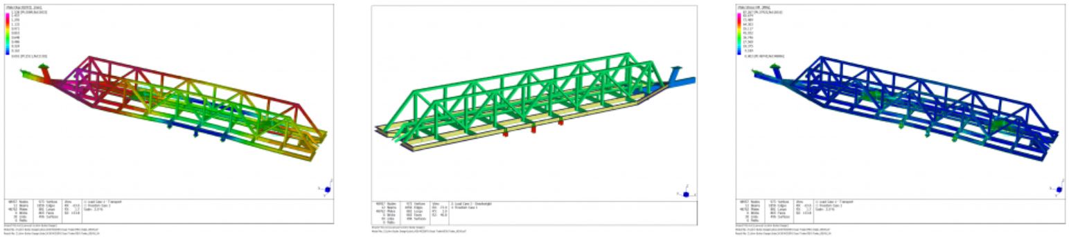
Mini Dyad Trailer
Minidyads are used by the Navy for mine recovering training; they are long and cylindrical in shape. So that they can be transported between sites a custom trailer was required to be designed. As the trailer was to be used on local roads and highways, it needed to be designed to the appropriate standard; National Code of Practice: Building Small Trailers.
A finite element model of the trailer was used to analyse the trailer structure under several loading conditions including transport and braking. Static and dynamic loads were applied to the model to simulate these conditions.
Based on the results of the finite element analysis, the fabrication drawings were developed. A maintenance and inspection schedule was also provided.
Police Boat WP23
Noakes approached John Butler Design to assist with the survey and maintenance management of the NSW Police boat fleet.
Over the course of the year the fleet needs regular servicing and upkeep, and is also required to to uphold the periodic survey schedule as part of their respective commercial survey applications.
This consists of undertaking lightship checks on the vessels to ensure the VCG and displacement are within the limits to continue operating under the current stability book. Otherwise an inclining experiment will be undertaken. However the nature of these vessels is such that they are run in a organised and methodical manner, meaning there is negligible weight gain and thus far resulting in predictable outcomes.

SMB John Gowland Inclining
JBD was engaged by BAE Systems in September to conduct the SMB JOHN GOWLAND inclining experiment so that the stability booklet could be renewed. As part of this process the lifting points of the vessel were re-certified. The experiment was witnessed by BAE Systems (RPEQ representative) and Qinetiq (Navy Technical Bureau representative).

LLC Inclining
JBD is reagularly approached by BAE Systems to carry out inclining experiments on the LLC vessels. These have previously been conducted at HMAS WATERHEN and HMAS KUTTABUL. These experiments are witnesed by either Qinetiq (on behalf of the Navy Technical Bureau, NTB) or a NTB representative. The vessels crew assists our team perform the solid state and liquid state surveys. The weight movements are then carried out with readings taken for each weight movement at the pendulum. Draft measurements, water temperature and density readings are taken before and after the weight movements.

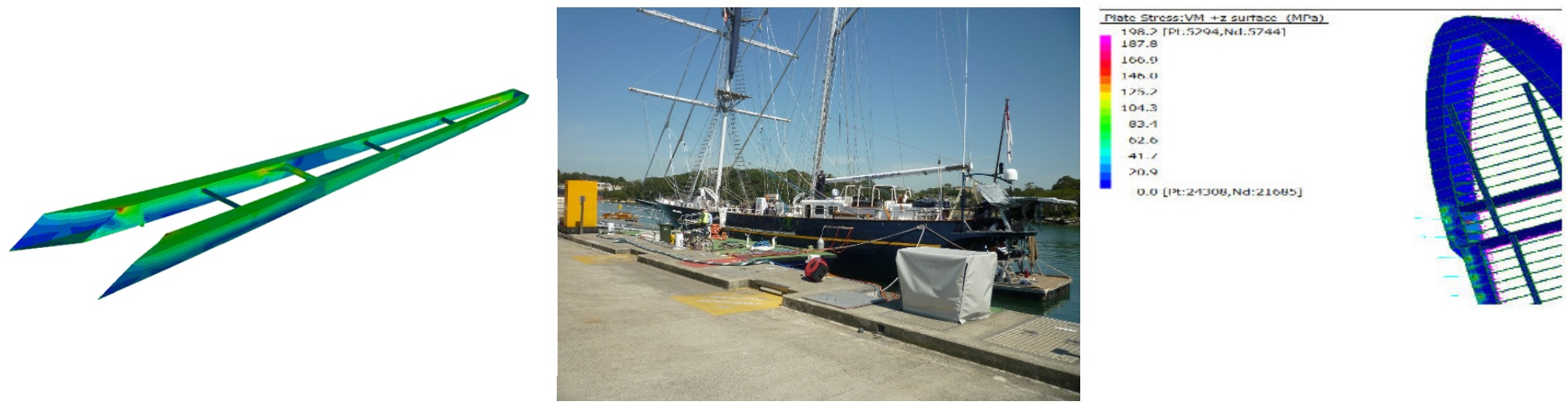
STS Young Endeavour Inclining
In November 2014 JBD was approached by Thales to undertake the inclining experiment on the STS YOUNG ENDEAVOUR so that the stability booklet could be updated to reflect the changes in mass and centre of gravity due to a newly installed mast and other refit items required for the vessel’s round the world trip.
The John Butler Design team carried out the experiment at Garden Island, witnessed by The Navy Technical Bureau (formerly The Directorate of Naval Platform Systems) and Thales. Solid state and liquid state surveys were performed by the team with the assistance from the vessels crew. The weight movements were then carried out with successful readings taken for each movement at the FWD and aft pendulums. Draft measurements, water temperature and density readings were taken before and after the weight movements.
The data taken on the day was used to successfully calculate the new lightship particulars. This was then passed to DNPS who subsequently updated the stability booklet.
Given the success of the experiment and JBD has recently been asked to carry out the vessels upcoming periodic inclining experiment which will be carried out later this year.

ASC Block Lifting
The Air Warfare Destroyers built by ASC are fabricated in modules that are generally built upside down , and then turned over, completed and then consolidated with other modules.
Prior to the lifting and handling operations being undertaken, a finite element analysis is undertaken to confirm the module is strong enough , and that the tensions in the lifting slings will not exceed the capacity of the lifting lugs. This analysis then needs to be independently certified to ensure it is safe to proceed with the lift operation.
John Butler gained extensive experience in preparing the lifting and handling calculations for these modules whilst at BCTQ. John Butler Design has continued to assist ASC with certification of their lift operations, independently verifying ASC’s stress and buckling calculations for B705 and B707 during their lifting and rotation on the rollover beams.
STS Young Endeavour Attachment Point
As part of the mast replacement process on STS Young Endeavour, an assessment was undertaken on the standing rigging tangs, hull chain plates, bowsprit and underdeck structure to verify that they had sufficient strength to withstand the breaking loads of the modified standing rigging.
The SWL and breaking load of each tang on the mast was determined by first principles analysis of the failure methods. These loads were compared with the breaking loads of the rigging that was attached to those tangs; the minimum factor of safety in accordance with Lloyds Register regulations was 1.2.
A structural assessment was also undertaken on the chain plates, bow sprit and hull structure using finite element analysis methods. A structural model was prepared, to which the breaking loads of the standing rigging were applied. The induced stresses were determined and compared with the ultimate strength of the materials to ensure there was sufficient factor of safety.
Landing Jack Certification
Following the failure of a landing jack on a heavy boat trailer, a superior replacement landing jack was required to be fitted. As part of this process, the capacity of the landing jack needed to be independently certified.
As no detailed information was available from the manufacturer, two of the chosen landing jacks were purchased, one to install and another to disassemble and measure of all of the components. Once the second one had been disassembled and measured, a 3D model of the landing jack was prepared and converted into a structural model.
The maximum capacity of the landing jack was determined using this structural model, and compared with the capacity specified by the manufacturer. The structural analysis was conducted using First principles verification for the capacity of the threaded rod and shear pin components of the landing jack and Finite Element Analysis for the remainder. The stress within the components of the jack was predicted during static and lifting load scenarios.
A detailed part drawing of the landing jack was also prepared to detail the internal structure and to use for future maintenance.

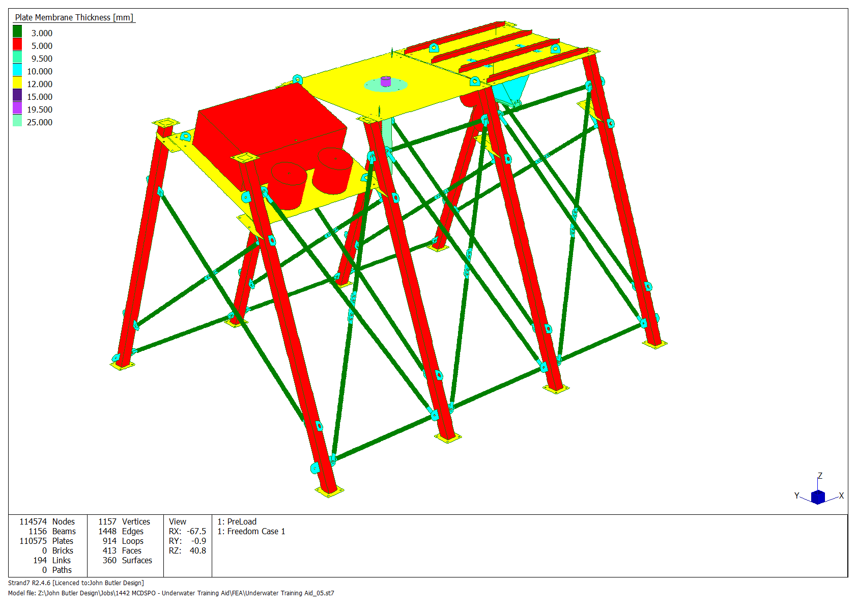
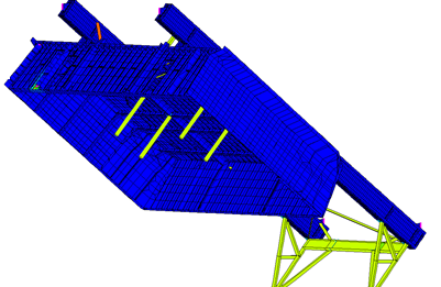
Underwater Training Aid
DMO requested John Butler Design perform an engineering assessment on a proposed design for an underwater training aid to be used by clearance divers, ships divers and army work divers during training. The training aid is intended to simulate working on, and carrying out tasks on a ship’s hull. The training aid consists of three bays simulating a propeller, a log probe and a sea chest, and may be assembled either on shore or underwater.
A review of the proposed design drawings was undertaken and comments given as to their completeness and suitability for production. A finite element model was then created to assess the structures’ ability to withstand current and wave forces whilst submerged.
A user manual describing the assembly steps required, maintenance routines and risk assessment as well as a design certificate confirming that the design is fit for purpose was also provided.